
Automated gate systems serve as critical access control points for commercial properties, residential communities, industrial facilities, and institutional campuses where vehicle entry requires regulation and security monitoring. Property managers, facility directors, and security operations teams increasingly recognize that gate automation alone provides incomplete protection without coordinated traffic calming measures that ensure vehicles approach and pass through gate areas at safe, controlled speeds. Speed bumps strategically positioned before, after, and sometimes within automated gate zones create physical speed control that protects gate equipment from collision damage, ensures adequate stopping distance for credential verification, and reduces liability exposure from vehicles entering pedestrian areas at excessive speeds. Successful integration of speed bumps with automated gates requires careful planning that addresses vehicle approach speeds, stopping distances, equipment protection zones, and user experience considerations that balance security effectiveness with operational convenience.
Understanding the Need for Speed Control at Gate Areas
Automated gates create natural stopping points where vehicles must pause for credential presentation, security screening, or remote authorization before proceeding. However, drivers approaching these locations at excessive speeds create multiple safety and operational problems. High approach speeds reduce available reaction time when gates malfunction or fail to open as expected, increasing collision risk that damages expensive gate equipment and creates safety hazards for occupants and nearby pedestrians. Rapid vehicle approaches also compromise security screening effectiveness, as security personnel have insufficient time to visually inspect vehicles or verify that credential presentations match vehicle occupants.
Beyond security concerns, excessive speeds through gate areas endanger pedestrians including security guards, maintenance personnel, and visitors who may be walking near gate zones. Parking areas, loading docks, and building entrances typically located immediately beyond security gates concentrate pedestrian traffic in areas where speeding vehicles pose serious injury risks. Property owners and facility managers bear legal responsibility for maintaining reasonably safe premises, with inadequate speed control measures representing potential negligence if injuries occur from foreseeable speeding hazards.
Strategic Speed Bump Placement Principles
Effective speed bump integration requires understanding how bump placement relative to gate positions influences driver behavior, vehicle flow, and overall system performance. Multiple placement zones serve distinct purposes within comprehensive gate area traffic management strategies.
Pre-Gate Speed Reduction Zones
The primary speed bump placement zone begins at distances ranging from 50 to 100 feet before automated gates, establishing initial speed reduction that prepares drivers for gate interaction. Bumps positioned in this zone reduce approach speeds from typical parking lot travel speeds of 15 to 25 mph down to controlled speeds of 5 to 10 mph appropriate for safe gate approach. This initial speed reduction provides drivers adequate distance to decelerate comfortably without harsh braking while creating sufficient reaction time to respond to gate status indicators showing whether gates are opening, closed, or experiencing operational problems.
Multiple speed bumps spaced at 30 to 50-foot intervals through approach zones create progressive speed reduction that feels natural to drivers rather than forcing abrupt deceleration at single choke points. Gradual speed reduction improves user experience and increases compliance compared to aggressive single bumps that drivers may attempt to circumvent or traverse at unsafe speeds. Facility managers should consider traffic volumes and typical approach speeds when determining how many pre-gate bumps are necessary, with higher-speed approach routes requiring more extensive speed reduction infrastructure.
Immediate Gate Area Protection
Secondary speed bump placement occurs within 10 to 20 feet before gate threshold positions, creating final speed control ensuring that vehicles cannot strike closed gates with sufficient force to cause damage. These close-proximity bumps serve as last-resort protection when drivers fail to observe gate status or mistakenly believe gates will open when they actually remain closed. The proximity to gates means that even if vehicles traverse bumps at moderate speeds, limited distance to gates prevents acceleration to damaging velocities before potential collision.
Bump placement in immediate gate areas requires careful coordination with gate opening mechanisms, sensor zones, and safety systems. Bumps must not interfere with vehicle detection sensors that trigger gate opening sequences, photocell safety systems that detect obstructions in gate swing paths, or drainage systems that manage water flow through gate areas. Engineering coordination between speed bump installers and gate system technicians ensures that traffic calming infrastructure complements rather than compromises gate functionality.
Post-Gate Speed Control
Speed bumps positioned 20 to 50 feet beyond gates prevent vehicles from accelerating rapidly after clearing security checkpoints, maintaining controlled speeds as vehicles enter parking areas, loading zones, or building approaches where pedestrian traffic concentrations create heightened safety requirements. Post-gate speed control proves particularly important at facilities where pedestrian walkways cross vehicle paths immediately beyond security gates or where building entrances sit adjacent to vehicle circulation routes.
Some facilities omit post-gate speed bumps when vehicle paths beyond gates lead directly to individual parking spaces where drivers naturally decelerate for parking maneuvers. However, facilities with through-traffic beyond gates that enables vehicles to maintain speed generally benefit from post-gate bumps maintaining the controlled speed environment established in approach zones.
Speed Bump Design Specifications for Gate Applications
Speed bump physical characteristics including height, width, profile geometry, and material composition significantly influence effectiveness, user comfort, and long-term durability. Facility managers specifying speed bumps for gate integration should understand how design parameters affect performance to make informed procurement decisions.
Height and Profile Selection
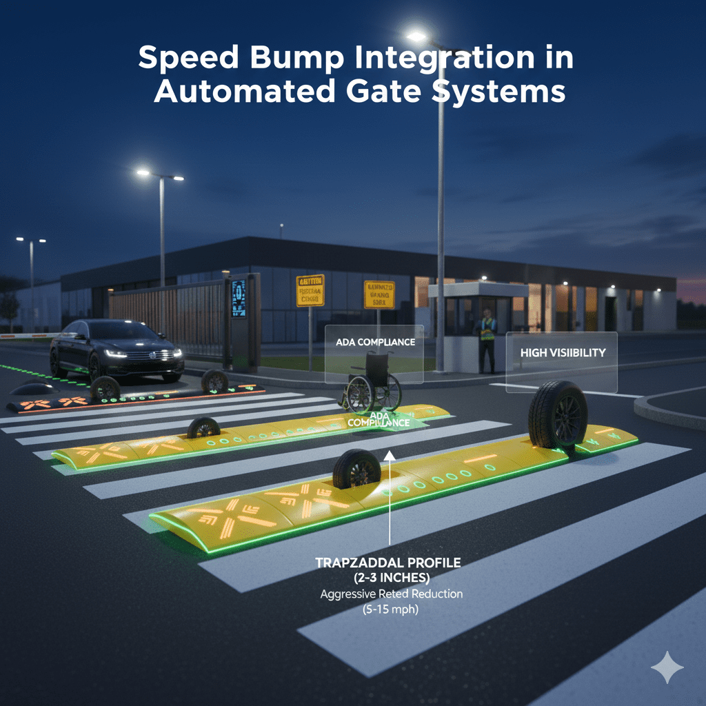
Speed bump height represents the most critical design parameter influencing vehicle speed reduction effectiveness and driver comfort. Standard speed bumps measure 3 to 4 inches in height, providing substantial speed reduction forcing drivers to slow to 5 to 15 mph depending on vehicle suspension characteristics and driver tolerance for discomfort. Lower-profile speed humps measuring 2 to 3 inches offer gentler speed control appropriate for areas where complete deceleration to near-stopping speeds proves unnecessary, such as approach zones where target speeds of 10 to 15 mph provide adequate control.
Profile geometry determines how abruptly vehicles experience vertical displacement when traversing bumps. Parabolic or rounded profiles create gentler transitions compared to trapezoidal designs with flat tops and angled sides. Gate area applications typically favor rounded profiles that provide adequate speed reduction while minimizing vehicle jolting that could cause discomfort for occupants or shift cargo in commercial vehicles. However, some facilities intentionally specify aggressive trapezoidal profiles in critical control zones where maximum speed enforcement takes priority over comfort considerations.
Width and Coverage Considerations
Speed bump width must span the full vehicle travel path to prevent drivers from steering around bump edges, which would completely defeat speed control purposes. Standard installation practice requires bumps extending from curb to curb or edge of pavement to edge, with end treatments that prevent vehicles from cutting corners to avoid bumps. Some installations incorporate wheel-track designs with two parallel raised sections separated by flat center sections, allowing certain vehicle types including ambulances and fire trucks to straddle bumps for emergency response purposes while still affecting standard passenger vehicles.
Gate approach lanes typically measure 10 to 14 feet wide, requiring speed bumps of corresponding length. Procurement specifications should verify that selected bump products provide adequate length for specific installation widths, noting that some modular bump systems require purchasing multiple segments to achieve necessary coverage. Facilities with dual-lane gate systems require wider bumps or coordinated installation of multiple bump units spanning both traffic lanes.
Material Options and Durability
Speed bumps come in several material categories, each offering distinct advantages and limitations relevant to gate area applications. Recycled rubber bumps provide economical solutions with good durability and relatively simple installation using anchor bolts or adhesive systems. Rubber’s inherent flexibility enables bumps to withstand vehicle impacts and temperature variations without cracking, though prolonged sun exposure can degrade materials requiring periodic replacement after 5 to 10 years of service.
Molded plastic bumps offer lightweight alternatives with bright colors and optional reflective elements enhancing visibility. Plastic materials resist petroleum products and chemicals that might degrade rubber, making plastic bumps preferable for industrial facilities where vehicles may leak fluids. However, plastic bumps can become brittle in extreme cold temperatures and may crack under heavy vehicle loads, limiting suitability for facilities serving large trucks or heavy equipment.
Asphalt or concrete speed bumps formed during pavement installation or constructed from poured materials provide permanent solutions with superior durability compared to modular products. These permanent bumps withstand all vehicle types and weather conditions indefinitely, though installation requires specialized paving contractors and alterations prove difficult if bump removal or relocation becomes necessary. Permanent bumps suit established gate installations with unlikely future modifications, while modular products offer flexibility for facilities anticipating potential gate system changes.

Integration with Gate Operation Sequences
Speed bumps influence how vehicles interact with automated gate systems, affecting required sensor placement, timing sequences, and safety system configurations. Facility managers must coordinate speed bump installation with gate system designers to ensure compatible operation.
Vehicle Detection and Gate Triggering
Most automated gate systems employ vehicle detection sensors that trigger gate opening when vehicles approach. Common sensor types include inductive loops embedded in pavement, above-ground magnetic sensors, and radar or video detection systems. Speed bump placement must not interfere with sensor detection zones while ensuring that bumps force vehicles to decelerate before reaching sensor activation points. This sequencing enables gates to begin opening while vehicles traverse speed bumps, allowing gates to reach fully open positions by the time vehicles complete bump passage and resume normal speed.
Improperly coordinated installations where speed bumps sit beyond sensor locations force drivers to stop completely at closed gates, wait for opening sequences to complete, then traverse speed bumps from stopped positions. This arrangement frustrates drivers and creates unnecessary traffic backups during high-volume periods. Optimal design places primary vehicle detection sensors at or slightly before first speed bump positions, initiating gate opening during bump passage so gates open before vehicles reach threshold positions.
Safety Systems and Obstruction Detection
Automated gates incorporate multiple safety systems preventing gate closing on vehicles or pedestrians in gate paths. Photocell sensors projecting infrared beams across gate openings detect obstructions and halt closing sequences until paths clear. Safety edge sensors mounted on gate leading edges detect physical contact and immediately reverse gate motion preventing crushing injuries. Speed bumps must not interfere with these safety systems while ensuring that gate closing sequences cannot initiate while vehicles remain on bumps unable to clear gate zones quickly.
Conservative gate control programming should delay closing initiation until vehicles completely clear speed bump zones beyond gates, preventing situations where gates begin closing while vehicles struggle to accelerate from bump passage. Adequate delay timers, typically 3 to 5 seconds after vehicle passage, provide safety margins ensuring gates remain open until vehicles fully exit gate areas.
Pedestrian Considerations and Crosswalk Integration
Many gate areas include pedestrian walkways, crosswalks, or guard stations where personnel circulate near vehicle paths. Speed bump integration should address pedestrian safety without creating trip hazards or accessibility barriers for individuals with mobility limitations.
ADA Compliance and Accessibility
The Americans with Disabilities Act (ADA) establishes accessibility requirements for pedestrian routes, including provisions addressing changes in elevation that could impede wheelchair users or individuals using mobility assistance devices. Speed bumps crossing pedestrian walkways must not create slopes exceeding ADA limits or present abrupt elevation changes constituting barriers to access. Facilities must provide accessible pedestrian routes that either avoid speed bumps entirely through separate walkways or incorporate compliant transitions with gentle slopes meeting accessibility standards.
Some speed bump designs include ramped end sections specifically engineered for ADA compliance, enabling wheelchair users to cross bumps via compliant slopes while maintaining vehicle speed control. Facilities unable to achieve compliant pedestrian crossings over speed bumps should route pedestrian paths around bump ends or provide separate accessible walkways isolated from vehicle traffic.
Visibility and Lighting Considerations
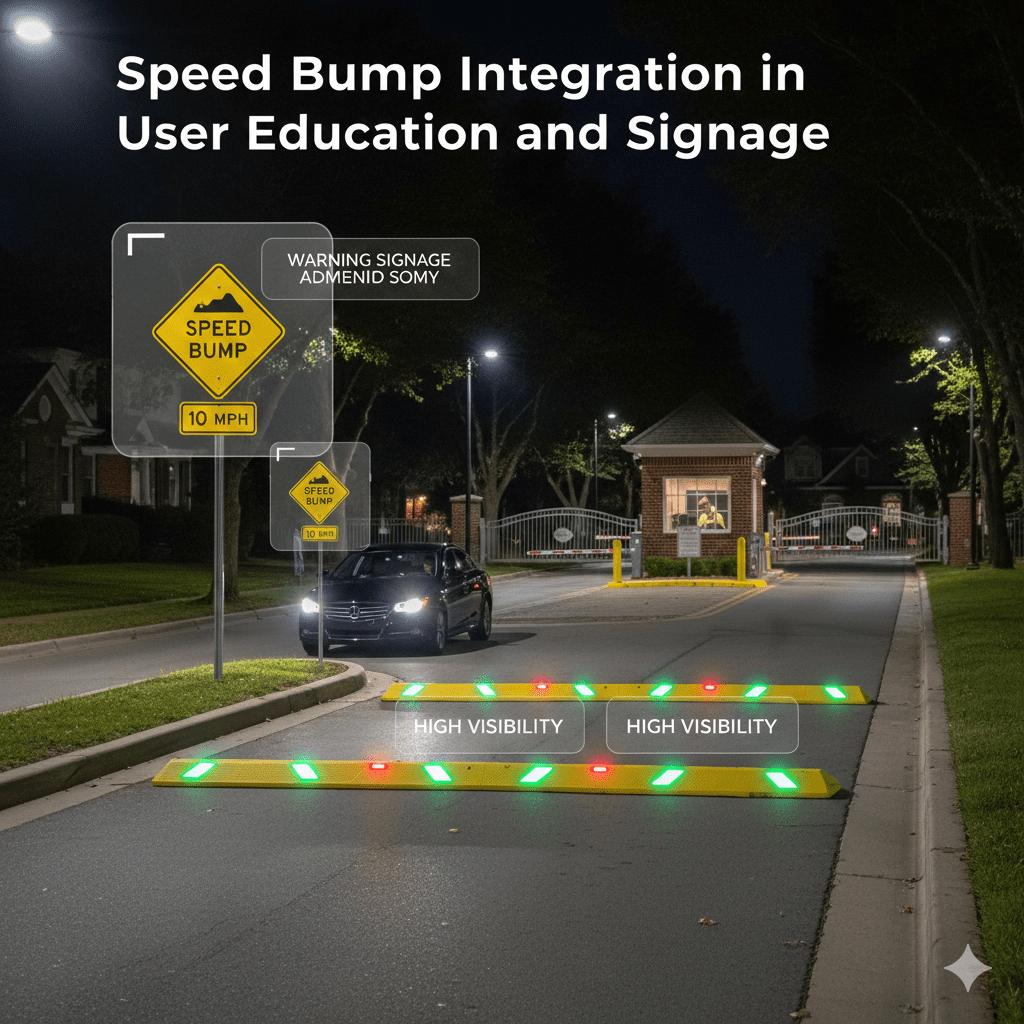
Speed bumps represent elevation changes and potential trip hazards requiring adequate visibility for both drivers and pedestrians. High-visibility yellow coloration represents standard practice, with reflective strips or raised pavement markers enhancing nighttime visibility under vehicle headlight illumination. Gate areas should maintain adequate lighting ensuring that speed bumps remain clearly visible during evening and nighttime hours when reduced visibility increases collision and trip risks.
Pedestrian crossing areas near speed bumps benefit from enhanced lighting and contrasting pavement markings that clearly delineate safe crossing zones. Warning signage alerting pedestrians to vehicle traffic and advising drivers of pedestrian crossing locations creates multilayered communication supporting safe interaction between vehicles and pedestrians in gate areas.
Drainage and Weather Considerations
Speed bumps alter surface water flow patterns in gate areas, potentially creating drainage problems if not properly addressed during installation. Water accumulation before bumps creates hazardous icing conditions in freezing weather and standing water that vehicles must splash through during rain events.
Drainage Channel Integration
Proper speed bump installation incorporates drainage channels or gaps enabling water to flow through or around bumps rather than pooling against bump faces. Some bump designs include integrated drainage channels molded into bump structures, while others rely on gaps between bump segments or channels cut through pavement adjacent to bump ends. Facilities in high-rainfall regions should prioritize bump designs with robust drainage features preventing water accumulation that could damage pavements, create hydroplaning hazards, or contribute to premature bump deterioration from freeze-thaw cycles.
Gate area drainage systems should be evaluated before speed bump installation to ensure that bumps will not obstruct existing drainage patterns. Facilities with poor existing drainage may require drainage improvements implemented concurrently with speed bump installation, including catch basin additions, channel cutting, or grading modifications that maintain positive drainage throughout gate areas.
Cold Climate Performance
Facilities in regions experiencing freezing temperatures must consider how speed bumps perform in winter conditions. Rubber and plastic bumps can become rigid in extreme cold, creating harsher ride characteristics and potentially increasing vehicle suspension stress. Ice and snow accumulation on bumps reduces visibility and creates slippery surfaces where drivers may lose traction when accelerating from bump passage.
Snow removal equipment can damage speed bumps, particularly modular units attached to pavement surfaces that plow blades may strike and dislodge. Facilities in snow-prone regions should consider recessed bump installations where bump tops sit flush with surrounding pavement or permanent concrete bumps that withstand snowplow contact without damage. Maintenance procedures should include winter bump inspection protocols verifying that bumps remain securely attached and clearly visible despite snow and ice exposure.
Maintenance Requirements and Lifecycle Management
Speed bumps require ongoing maintenance preserving functionality, visibility, and structural integrity throughout their service lives. Facility maintenance teams should implement systematic inspection and maintenance programs addressing common bump deterioration modes.
Inspection and Repair Protocols
Quarterly visual inspections should evaluate bump condition including secure attachment to pavement surfaces, visible cracking or material deterioration, and adequacy of visible markings and reflective elements. Rubber and plastic bumps may separate from pavements as adhesives fail or anchor bolts loosen from repeated vehicle impacts and thermal cycling. Prompt reattachment of loose bumps prevents progressive damage that could necessitate complete bump replacement.
Reflective markings and high-visibility coloration degrade from sun exposure and abrasion from vehicle tires, requiring periodic refresh to maintain adequate visibility. Re-striping with reflective paint or replacement of adhesive reflective tape represents relatively simple maintenance tasks that dramatically improve bump visibility and safety effectiveness.
Replacement Planning and Budgeting
Even well-maintained speed bumps eventually require replacement as materials degrade beyond effective repair. Rubber bumps typically provide 5 to 10 years of service before requiring replacement, while plastic bumps may last 3 to 7 years depending on traffic volumes and climate exposure. Permanent concrete or asphalt bumps can last indefinitely with minor surface repairs but may require removal and reconstruction if facility modifications necessitate bump relocation.
Facility capital planning should include periodic speed bump replacement budgets reflecting expected service life and replacement costs. Bulk procurement of replacement bumps for multi-location facilities can achieve favorable pricing while ensuring consistent product specifications across all installations. Maintaining spare bump inventory enables rapid replacement when failures occur, preventing extended periods with non-functional speed control.
User Education and Signage
Even well-designed and properly installed speed bumps prove ineffective if drivers remain unaware of their presence until immediately upon them, potentially causing emergency braking that creates rear-end collision risks or damages vehicles. Advance warning signage and driver education programs support effective speed bump integration.
Warning Signage Requirements
Standard traffic control practice requires advance warning signs positioned 50 to 100 feet before speed bumps, alerting drivers to reduce speed in preparation for bump passage. MUTCD provides standardized warning sign designs featuring speed bump symbols and supplemental speed advisory plaques recommending safe traversal speeds, typically 5 to 15 mph depending on bump characteristics. Facilities should install compliant warning signage meeting size, color, and retroreflectivity standards ensuring adequate visibility day and night.
Some facilities implement multi-stage warning progressions including preliminary signs at greater distances followed by immediate warning signs just before bump locations. This layered approach proves particularly valuable for facilities with high-speed approach routes where drivers require extended warning distances to decelerate comfortably.
Community Communication Programs
Residential communities, corporate campuses, and institutional facilities benefit from proactive communication programs informing residents, employees, and regular visitors about speed bump installations and their safety purposes. Communication methods include email notifications, website announcements, posted notices at community centers or building lobbies, and information included in new resident or employee orientation materials.
Clear communication explaining why speed bumps were installed and how they improve safety reduces complaints and builds support for traffic calming measures. Facilities experiencing resistance to speed bumps should emphasize security benefits, pedestrian safety improvements, and gate equipment protection that bump installations provide, framing speed calming as essential components of comprehensive facility safety programs.
Cost Considerations and Budget Planning
Speed bump integration with automated gate systems involves several cost categories including bump procurement, installation labor, pavement modifications, and ongoing maintenance. Comprehensive budget planning should account for all lifecycle costs rather than focusing solely on initial procurement expenses.
Product Costs and Installation Expenses
Modular rubber or plastic speed bumps typically cost $100 to $300 per 6-foot section depending on design features and quality grades, with typical gate approach installations requiring 2 to 6 bump units costing $200 to $1,800 in materials. Installation labor adds $200 to $600 per bump depending on whether simple surface mounting or more complex installation with pavement cutting and anchor embedment occurs. Total project costs for comprehensive gate area speed bump integration typically range from $1,000 to $5,000 per gate location.
Permanent asphalt or concrete bumps cost more for initial installation, typically $500 to $1,500 per bump including material and specialized paving contractor labor, but provide superior longevity potentially justifying higher upfront investment. Facilities should evaluate total ownership costs over 10 to 20-year planning horizons, considering replacement frequency for modular products versus longer-lived permanent installations.
Return on Investment Through Risk Reduction
Speed bump investments deliver returns through multiple mechanisms including reduced gate equipment damage, decreased liability exposure from pedestrian injuries, and improved security screening effectiveness. Single gate collision incidents requiring equipment replacement can cost $5,000 to $15,000, easily justifying speed bump investments that prevent such damage. More significantly, serious pedestrian injuries from speeding vehicles can generate legal judgments or settlements exceeding $100,000, making speed control measures highly cost-effective risk management tools.
Insurance carriers increasingly recognize traffic calming benefits when underwriting premises liability policies, with some insurers offering premium reductions for facilities implementing comprehensive speed control measures. Facilities should inform insurance brokers about speed bump installations to potentially capture premium savings that help offset implementation costs.
Conclusion: Comprehensive Gate Area Safety Through Speed Integration
Speed bump integration represents essential components of comprehensive automated gate security and safety systems, providing physical speed control that protects equipment, enhances security effectiveness, and reduces liability exposure through improved pedestrian safety. Property managers and facility directors who approach speed bump integration systematically through careful placement planning, appropriate design specification, coordination with gate operations, and ongoing maintenance create safer, more effective gate environments that serve both security and operational objectives. While speed bumps require modest investments and create some user inconvenience through required deceleration, these tradeoffs prove worthwhile given substantial safety benefits and risk reduction that proper speed control provides. Facilities prioritizing safety and operational excellence recognize speed bump integration not as optional enhancement but as fundamental requirement for responsible gate area management.
Looking for a Custom Speed Bumps Manufacturer or Supplier? Struggling to find the right factory to bring your vision to life? We’ve got you covered! At our place, we craft top-quality Speed Bumps with precision and care. Big or small, your needs are our mission. Let’s launch your Speed Bumps project and take your product line to the next level! Click here to contact